

What Is The Power In Diopters Of A Camera Lens That Has A 50.0 Mm Focal Length?
Geometric Optics
203 Image Formation by Lenses
Learning Objectives
- List the rules for ray tracking for thin lenses.
- Illustrate the formation of images using the technique of ray tracking.
- Make up one's mind power of a lens given the focal length.
Lenses are found in a huge array of optical instruments, ranging from a unproblematic magnifying glass to the center to a photographic camera's zoom lens. In this section, nosotros will utilize the constabulary of refraction to explore the properties of lenses and how they class images.
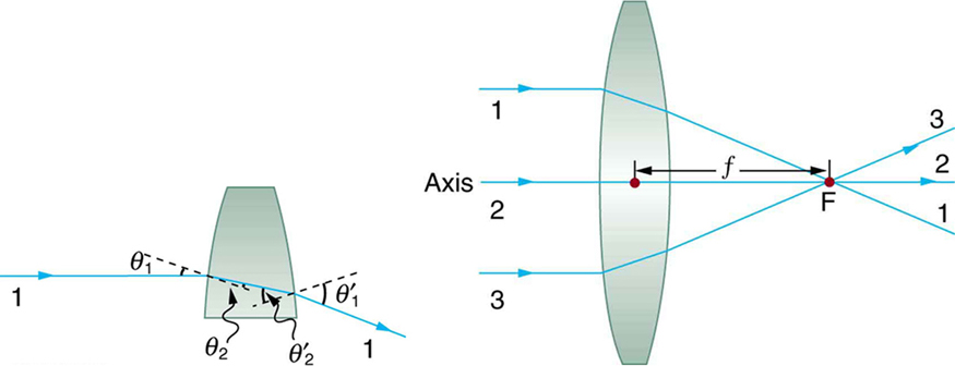
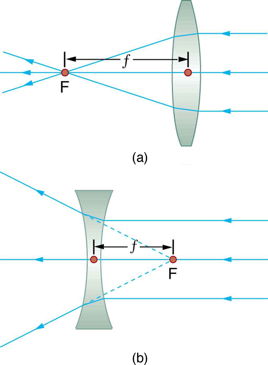
The word lens derives from the Latin discussion for a lentil bean, the shape of which is similar to the convex lens in (Figure). The convex lens shown has been shaped so that all light rays that enter it parallel to its axis cantankerous one another at a unmarried signal on the opposite side of the lens. (The axis is divers to be a line normal to the lens at its center, as shown in (Effigy).) Such a lens is chosen a converging (or convex) lens for the converging effect it has on light rays. An expanded view of the path of one ray through the lens is shown, to illustrate how the ray changes direction both as it enters and every bit it leaves the lens. Since the index of refraction of the lens is greater than that of air, the ray moves towards the perpendicular every bit it enters and abroad from the perpendicular as information technology leaves. (This is in accordance with the law of refraction.) Due to the lens's shape, calorie-free is thus bent toward the axis at both surfaces. The signal at which the rays cross is defined to exist the focal point F of the lens. The distance from the center of the lens to its focal point is divers to be the focal length  of the lens. (Figure) shows how a converging lens, such as that in a magnifying glass, can converge the virtually parallel light rays from the dominicus to a small spot.
Rays of light entering a converging lens parallel to its centrality converge at its focal signal F. (Ray 2 lies on the axis of the lens.) The distance from the center of the lens to the focal betoken is the lens's focal length . An expanded view of the path taken by ray i shows the perpendiculars and the angles of incidence and refraction at both surfaces.
Converging or Convex Lens
The lens in which light rays that enter it parallel to its axis cross one another at a single point on the opposite side with a converging effect is called converging lens.
Focal Point F
The betoken at which the light rays cross is called the focal betoken F of the lens.
Focal Length
The altitude from the center of the lens to its focal signal is chosen focal length .
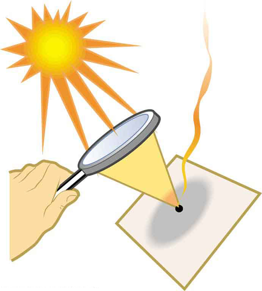
Sunlight focused by a converging magnifying drinking glass can burn newspaper. Light rays from the sun are most parallel and cantankerous at the focal point of the lens. The more powerful the lens, the closer to the lens the rays will cantankerous.
The greater effect a lens has on calorie-free rays, the more powerful information technology is said to be. For example, a powerful converging lens will focus parallel low-cal rays closer to itself and will have a smaller focal length than a weak lens. The lite volition also focus into a smaller and more intense spot for a more than powerful lens. The power  of a lens is defined to be the changed of its focal length. In equation form, this is

Power
The power of a lens is divers to be the inverse of its focal length. In equation form, this is

where is the focal length of the lens, which must be given in meters (and not cm or mm). The power of a lens has the unit diopters (D), provided that the focal length is given in meters. That is,  , or
, or  . (Annotation that this ability (optical power, really) is non the same as power in watts defined in Work, Energy, and Energy Resource. It is a concept related to the outcome of optical devices on light.) Optometrists prescribe common spectacles and contact lenses in units of diopters.
What is the Power of a Common Magnifying Glass?
Suppose you lot take a magnifying glass out on a sunny day and you lot detect that it concentrates sunlight to a small spot 8.00 cm away from the lens. What are the focal length and power of the lens?
Strategy
The state of affairs hither is the same equally those shown in (Effigy) and (Figure). The Dominicus is so far abroad that the Sun'southward rays are nigh parallel when they achieve Earth. The magnifying glass is a convex (or converging) lens, focusing the nearly parallel rays of sunlight. Thus the focal length of the lens is the distance from the lens to the spot, and its power is the inverse of this altitude (in k).
Solution
The focal length of the lens is the altitude from the eye of the lens to the spot, given to be 8.00 cm. Thus,

To find the ability of the lens, nosotros must first convert the focal length to meters; then, we substitute this value into the equation for power. This gives

Word
This is a relatively powerful lens. The power of a lens in diopters should not be confused with the familiar concept of power in watts. It is an unfortunate fact that the give-and-take "power" is used for two completely different concepts. If you examine a prescription for eyeglasses, you volition note lens powers given in diopters. If you examine the label on a motor, you volition note energy consumption rate given as a power in watts.
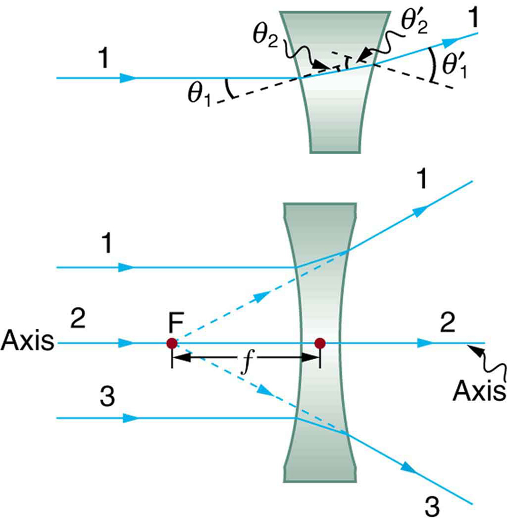
(Figure) shows a concave lens and the effect it has on rays of light that enter it parallel to its axis (the path taken by ray two in the figure is the centrality of the lens). The concave lens is a diverging lens, because information technology causes the light rays to bend away (diverge) from its centrality. In this case, the lens has been shaped and so that all light rays inbound it parallel to its axis appear to originate from the same point,  , defined to exist the focal point of a diverging lens. The distance from the center of the lens to the focal bespeak is over again called the focal length of the lens. Note that the focal length and ability of a diverging lens are divers to be negative. For case, if the distance to
  in (Figure) is v.00 cm, then the focal length is
  and the power of the lens is
  . An expanded view of the path of 1 ray through the lens is shown in the figure to illustrate how the shape of the lens, together with the law of refraction, causes the ray to follow its particular path and be diverged.
Rays of light entering a diverging lens parallel to its axis are diverged, and all appear to originate at its focal betoken . The dashed lines are not rays—they indicate the directions from which the rays appear to come. The focal length of a diverging lens is negative. An expanded view of the path taken past ray one shows the perpendiculars and the angles of incidence and refraction at both surfaces.
Diverging Lens
A lens that causes the light rays to bend away from its axis is chosen a diverging lens.
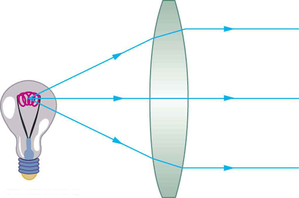
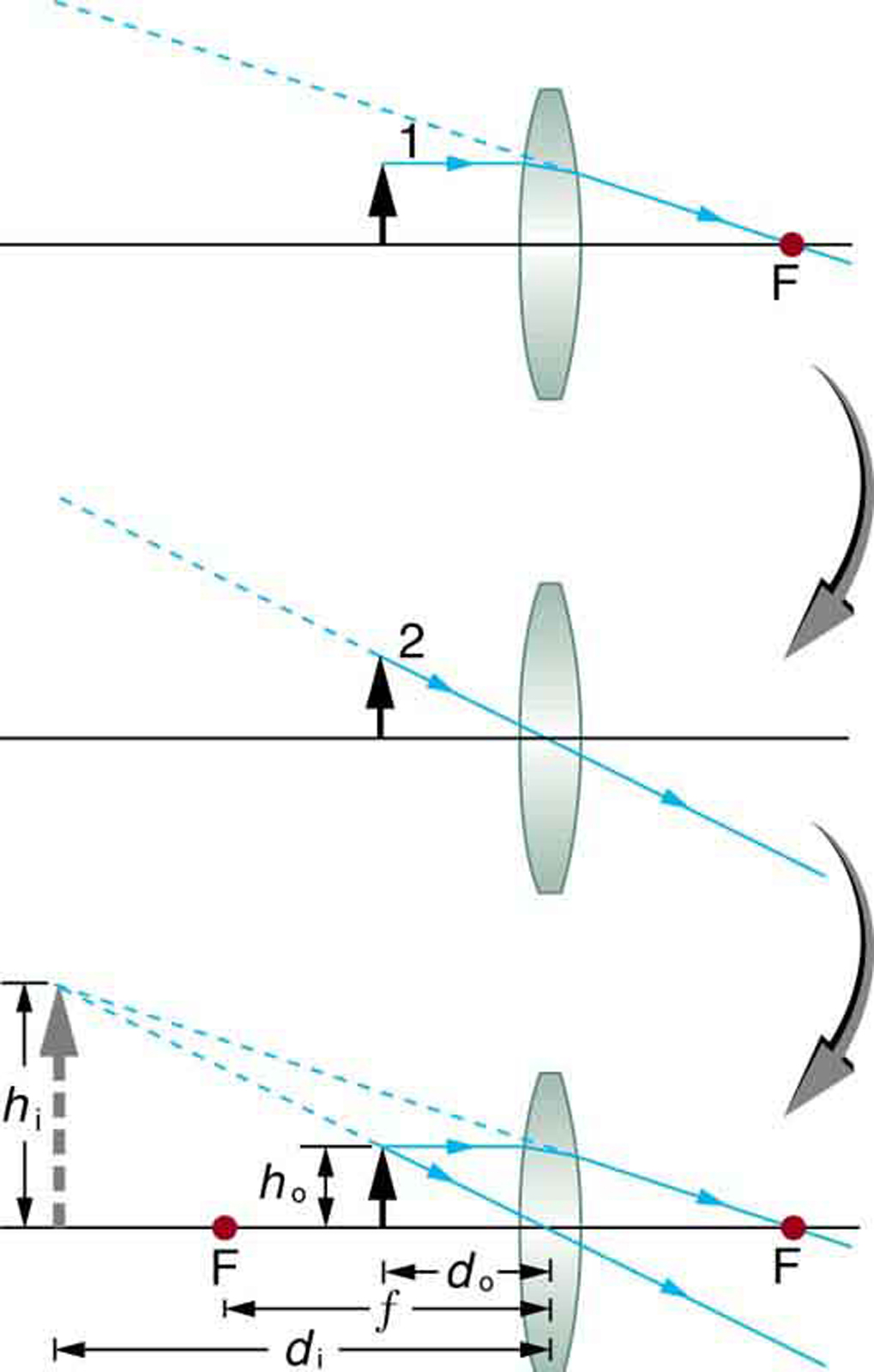
As noted in the initial discussion of the law of refraction in The Law of Refraction, the paths of low-cal rays are exactly reversible. This ways that the management of the arrows could be reversed for all of the rays in (Figure) and (Figure). For instance, if a point light source is placed at the focal point of a convex lens, equally shown in (Figure), parallel light rays emerge from the other side.
A modest light source, like a light bulb filament, placed at the focal signal of a convex lens, results in parallel rays of light emerging from the other side. The paths are exactly the reverse of those shown in (Effigy). This technique is used in lighthouses and sometimes in traffic lights to produce a directional beam of light from a source that emits calorie-free in all directions.
Ray Tracing and Thin Lenses
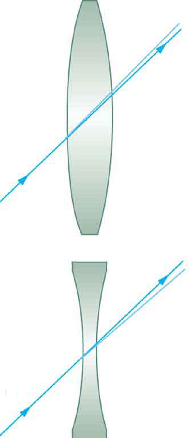
Ray tracing is the technique of determining or following (tracing) the paths that light rays have. For rays passing through matter, the law of refraction is used to trace the paths. Here nosotros use ray tracing to assist us understand the action of lenses in situations ranging from forming images on film to magnifying small-scale print to correcting nearsightedness. While ray tracing for complicated lenses, such equally those found in sophisticated cameras, may require estimator techniques, there is a gear up of simple rules for tracing rays through thin lenses. A thin lens is defined to be one whose thickness allows rays to refract, equally illustrated in (Figure), but does non allow properties such as dispersion and aberrations. An ideal thin lens has two refracting surfaces but the lens is thin enough to assume that calorie-free rays curve only in one case. A thin symmetrical lens has two focal points, i on either side and both at the aforementioned altitude from the lens. (Run into (Effigy).) Another important characteristic of a thin lens is that lite rays through its centre are deflected by a negligible amount, as seen in (Figure).
Thin Lens
A sparse lens is defined to be one whose thickness allows rays to refract but does not allow properties such as dispersion and aberrations.
Accept-Abode Experiment: A Visit to the Optician
Wait through your eyeglasses (or those of a friend) backward and forward and annotate on whether they deed like thin lenses.
Thin lenses have the same focal length on either side. (a) Parallel calorie-free rays entering a converging lens from the correct cross at its focal indicate on the left. (b) Parallel low-cal rays inbound a diverging lens from the correct seem to come from the focal indicate on the correct.
The light ray through the center of a sparse lens is deflected by a negligible amount and is assumed to emerge parallel to its original path (shown as a shaded line).
Using newspaper, pencil, and a direct edge, ray tracing tin can accurately describe the performance of a lens. The rules for ray tracing for thin lenses are based on the illustrations already discussed:
- A ray inbound a converging lens parallel to its axis passes through the focal point F of the lens on the other side. (Encounter rays i and 3 in (Effigy).)
- A ray entering a diverging lens parallel to its axis seems to come from the focal betoken F. (See rays ane and iii in (Figure).)
- A ray passing through the eye of either a converging or a diverging lens does not change management. (Encounter (Figure), and see ray ii in (Figure) and (Figure).)
- A ray entering a converging lens through its focal bespeak exits parallel to its centrality. (The contrary of rays 1 and 3 in (Figure).)
- A ray that enters a diverging lens by heading toward the focal point on the opposite side exits parallel to the centrality. (The reverse of rays 1 and 3 in (Effigy).)
Rules for Ray Tracing
- A ray entering a converging lens parallel to its axis passes through the focal point F of the lens on the other side.
- A ray entering a diverging lens parallel to its centrality seems to come from the focal signal F.
- A ray passing through the center of either a converging or a diverging lens does not change direction.
- A ray entering a converging lens through its focal betoken exits parallel to its axis.
- A ray that enters a diverging lens past heading toward the focal point on the contrary side exits parallel to the axis.
Image Formation past Sparse Lenses
In some circumstances, a lens forms an obvious paradigm, such as when a movie projector casts an image onto a screen. In other cases, the image is less obvious. Where, for example, is the image formed by eyeglasses? We volition utilise ray tracing for thin lenses to illustrate how they grade images, and nosotros volition develop equations to describe the paradigm formation quantitatively.
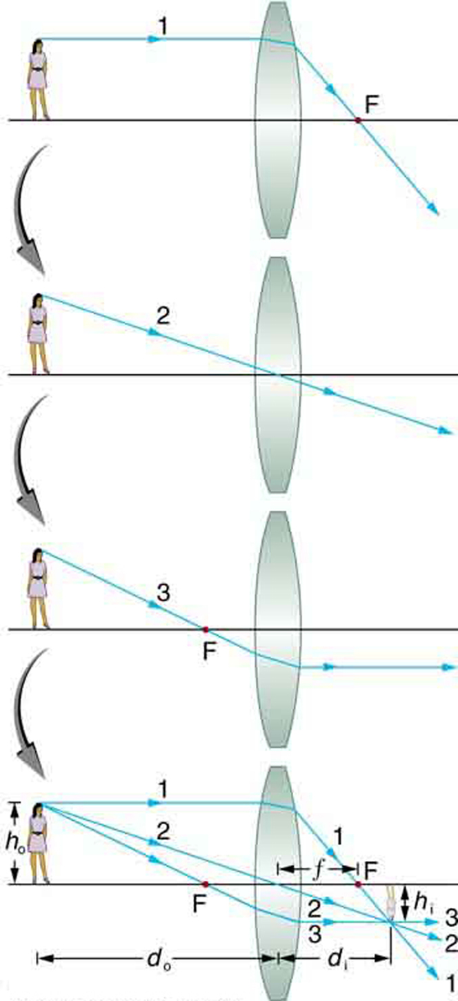
Consider an object some distance abroad from a converging lens, as shown in (Effigy). To detect the location and size of the paradigm formed, we trace the paths of selected light rays originating from one point on the object, in this example the top of the person's head. The figure shows three rays from the top of the object that tin exist traced using the ray tracing rules given in a higher place. (Rays leave this point going in many directions, but nosotros concentrate on merely a few with paths that are easy to trace.) The starting time ray is one that enters the lens parallel to its axis and passes through the focal point on the other side (rule 1). The second ray passes through the center of the lens without irresolute direction (rule 3). The third ray passes through the nearer focal bespeak on its way into the lens and leaves the lens parallel to its axis (rule iv). The iii rays cross at the same betoken on the other side of the lens. The prototype of the top of the person's caput is located at this point. All rays that come from the aforementioned betoken on the top of the person's head are refracted in such a way as to cantankerous at the betoken shown. Rays from another signal on the object, such every bit her belt buckle, volition also cross at another common point, forming a complete paradigm, as shown. Although three rays are traced in (Effigy), simply two are necessary to locate the image. It is all-time to trace rays for which at that place are simple ray tracing rules. Before applying ray tracing to other situations, permit us consider the example shown in (Figure) in more than detail.
Ray tracing is used to locate the prototype formed by a lens. Rays originating from the same point on the object are traced—the three chosen rays each follow one of the rules for ray tracing, so that their paths are piece of cake to decide. The paradigm is located at the bespeak where the rays cross. In this instance, a real image—one that can exist projected on a screen—is formed.
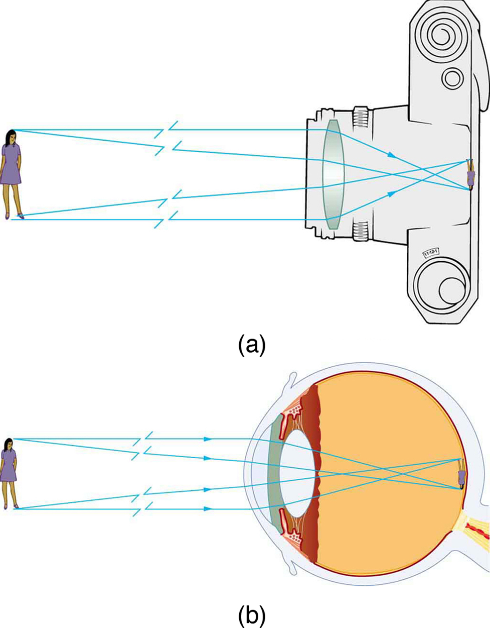
The image formed in (Figure) is a real image, meaning that it tin be projected. That is, light rays from 1 bespeak on the object actually cross at the location of the image and tin be projected onto a screen, a piece of motion-picture show, or the retina of an center, for example. (Effigy) shows how such an image would be projected onto movie past a camera lens. This effigy too shows how a real epitome is projected onto the retina by the lens of an eye. Note that the image is there whether it is projected onto a screen or not.
Real Image
The image in which calorie-free rays from one bespeak on the object actually cantankerous at the location of the image and can be projected onto a screen, a piece of film, or the retina of an eye is called a existent image.
Real images can exist projected. (a) A existent prototype of the person is projected onto motion-picture show. (b) The converging nature of the multiple surfaces that brand up the eye result in the project of a existent image on the retina.
Several important distances appear in (Effigy). We define  to exist the object distance, the altitude of an object from the eye of a lens. Epitome distance
  is defined to exist the distance of the image from the center of a lens. The height of the object and height of the image are given the symbols
  and
and  , respectively. Images that appear upright relative to the object have heights that are positive and those that are inverted accept negative heights. Using the rules of ray tracing and making a calibration drawing with paper and pencil, similar that in (Effigy), we can accurately describe the location and size of an prototype. But the real do good of ray tracing is in visualizing how images are formed in a diverseness of situations. To obtain numerical data, we use a pair of equations that tin be derived from a geometric analysis of ray tracing for thin lenses. The thin lens equations are

and

We define the ratio of prototype height to object elevation ( ) to be the magnification
  . (The minus sign in the equation above will exist discussed soon.) The sparse lens equations are broadly applicable to all situations involving thin lenses (and "sparse" mirrors, as we will see later). We will explore many features of prototype formation in the following worked examples.
Image Distance
The distance of the prototype from the heart of the lens is called image distance.
Thin Lens Equations and Magnification

Finding the Image of a Calorie-free Bulb Filament past Ray Tracing and by the Sparse Lens Equations
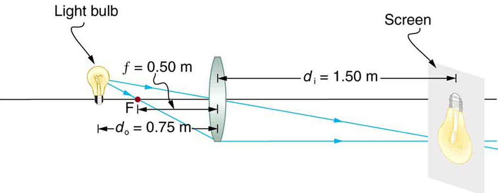
A clear glass low-cal bulb is placed 0.750 m from a convex lens having a 0.500 m focal length, as shown in (Effigy). Use ray tracing to get an approximate location for the prototype. Then use the thin lens equations to calculate (a) the location of the image and (b) its magnification. Verify that ray tracing and the thin lens equations produce consistent results.
A light bulb placed 0.750 m from a lens having a 0.500 k focal length produces a real image on a poster board as discussed in the case above. Ray tracing predicts the image location and size.
Strategy and Concept
Since the object is placed further abroad from a converging lens than the focal length of the lens, this situation is analogous to those illustrated in (Figure) and (Figure). Ray tracing to scale should produce similar results for . Numerical solutions for and can be obtained using the thin lens equations, noting that  .
.
Solutions (Ray tracing)
The ray tracing to scale in (Figure) shows two rays from a point on the bulb's filament crossing about 1.50 chiliad on the far side of the lens. Thus the image altitude is about 1.50 m. Similarly, the image height based on ray tracing is greater than the object tiptop by about a factor of 2, and the paradigm is inverted. Thus is about –2. The minus sign indicates that the image is inverted.
The thin lens equations can be used to observe from the given information:

Rearranging to isolate gives

Entering known quantities gives a value for  :
:

This must be inverted to discover :

Notation that another way to find is to rearrange the equation:
This yields the equation for the image distance as:

Notation that in that location is no inverting here.
The thin lens equations can be used to find the magnification , since both and are known. Inbound their values gives

Discussion
Annotation that the minus sign causes the magnification to exist negative when the paradigm is inverted. Ray tracing and the employ of the thin lens equations produce consistent results. The sparse lens equations give the nigh precise results, being express just by the accuracy of the given information. Ray tracing is limited past the accurateness with which you can draw, but information technology is highly useful both conceptually and visually.
Real images, such as the one considered in the previous example, are formed by converging lenses whenever an object is further from the lens than its focal length. This is true for movie projectors, cameras, and the middle. Nosotros shall refer to these as case 1 images. A case 1 prototype is formed when  and is positive, as in (Figure)(a). (A summary of the 3 cases or types of prototype germination appears at the end of this section.)
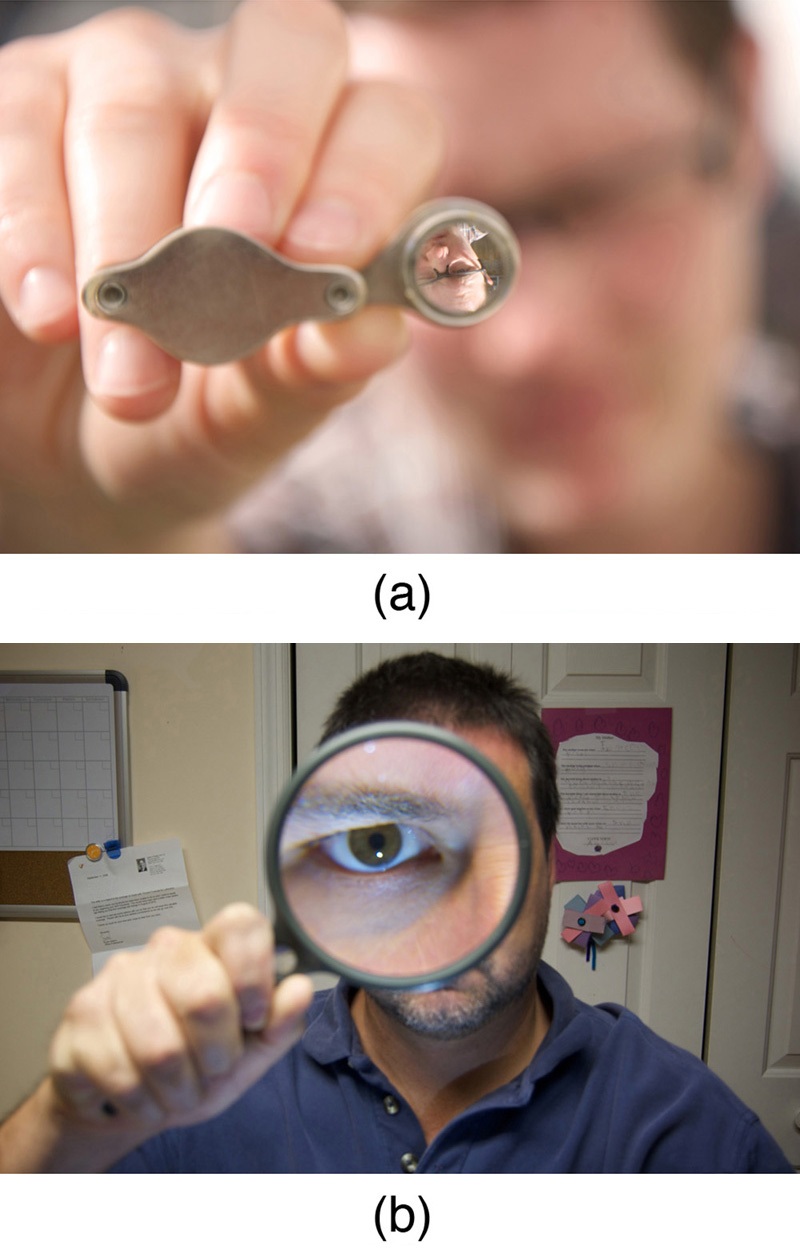
A unlike type of paradigm is formed when an object, such as a person'southward face, is held close to a convex lens. The image is upright and larger than the object, equally seen in (Effigy)(b), then the lens is called a magnifier. If y'all slowly pull the magnifier away from the face up, you will see that the magnification steadily increases until the image begins to mistiness. Pulling the magnifier fifty-fifty farther away produces an inverted epitome as seen in (Figure)(a). The altitude at which the image blurs, and across which it inverts, is the focal length of the lens. To utilize a convex lens as a magnifier, the object must be closer to the converging lens than its focal length. This is chosen a case 2 epitome. A case 2 prototype is formed when  and is positive.
(a) When a converging lens is held farther abroad from the face up than the lens's focal length, an inverted image is formed. This is a example 1 image. Annotation that the image is in focus but the confront is non, because the paradigm is much closer to the camera taking this photograph than the face up. (credit: DaMongMan, Flickr) (b) A magnified image of a confront is produced by placing information technology closer to the converging lens than its focal length. This is a case 2 prototype. (credit: Casey Fleser, Flickr)
(Effigy) uses ray tracing to prove how an prototype is formed when an object is held closer to a converging lens than its focal length. Rays coming from a mutual bespeak on the object continue to diverge after passing through the lens, but all announced to originate from a signal at the location of the image. The image is on the same side of the lens as the object and is farther abroad from the lens than the object. This epitome, similar all instance 2 images, cannot exist projected and, hence, is called a virtual prototype. Light rays simply announced to originate at a virtual epitome; they practice not actually pass through that location in space. A screen placed at the location of a virtual image will receive merely lengthened light from the object, non focused rays from the lens. Additionally, a screen placed on the opposite side of the lens volition receive rays that are notwithstanding diverging, and so no epitome will be projected on it. We can come across the magnified image with our eyes, because the lens of the center converges the rays into a existent image projected on our retina. Finally, we note that a virtual image is upright and larger than the object, meaning that the magnification is positive and greater than i.
Ray tracing predicts the image location and size for an object held closer to a converging lens than its focal length. Ray i enters parallel to the axis and exits through the focal point on the contrary side, while ray 2 passes through the center of the lens without irresolute path. The two rays continue to diverge on the other side of the lens, just both appear to come up from a mutual point, locating the upright, magnified, virtual image. This is a case 2 epitome.
Virtual Image
An image that is on the same side of the lens equally the object and cannot be projected on a screen is called a virtual paradigm.
Image Produced by a Magnifying Glass
Suppose the book page in (Figure) (a) is held vii.50 cm from a convex lens of focal length 10.0 cm, such as a typical magnifying glass might take. What magnification is produced?
Strategy and Concept
We are given that  and
and  , and then nosotros take a situation where the object is placed closer to the lens than its focal length. Nosotros therefore await to get a case 2 virtual image with a positive magnification that is greater than i. Ray tracing produces an image like that shown in (Figure), just we will utilize the thin lens equations to get numerical solutions in this example.
Solution
To find the magnification , we try to apply magnification equation,  . We exercise not have a value for , so that we must first discover the location of the prototype using lens equation. (The process is the same as followed in the preceding instance, where and were known.) Rearranging the magnification equation to isolate gives
Inbound known values, we obtain a value for :

This must be inverted to find :

Now the sparse lens equation tin be used to find the magnification , since both and are known. Entering their values gives

Discussion
A number of results in this example are true of all case 2 images, as well every bit existence consistent with (Figure). Magnification is indeed positive (as predicted), pregnant the prototype is upright. The magnification is likewise greater than one, meaning that the image is larger than the object—in this case, by a gene of 4. Note that the image distance is negative. This means the prototype is on the same side of the lens as the object. Thus the prototype cannot be projected and is virtual. (Negative values of occur for virtual images.) The image is farther from the lens than the object, since the paradigm distance is greater in magnitude than the object distance. The location of the image is not obvious when you look through a magnifier. In fact, since the prototype is bigger than the object, you may think the image is closer than the object. Merely the image is farther away, a fact that is useful in correcting farsightedness, as we shall encounter in a later department.
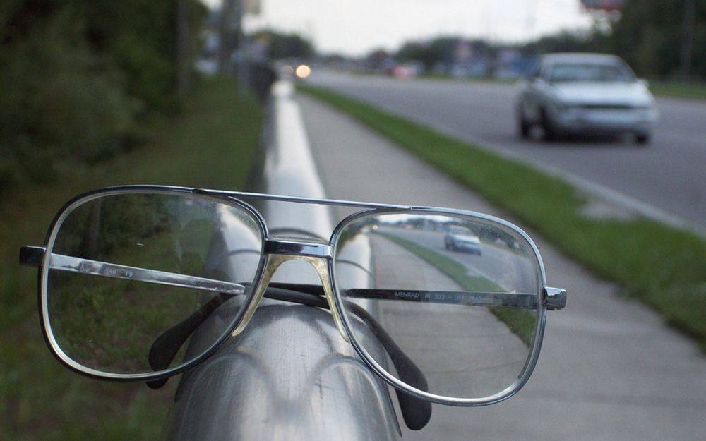
A third type of image is formed by a diverging or concave lens. Effort looking through eyeglasses meant to correct nearsightedness. (Run across (Figure).) You volition see an image that is upright only smaller than the object. This means that the magnification is positive but less than one. The ray diagram in (Figure) shows that the image is on the same side of the lens every bit the object and, hence, cannot be projected—information technology is a virtual prototype. Note that the image is closer to the lens than the object. This is a case 3 image, formed for any object past a negative focal length or diverging lens.
A car viewed through a concave or diverging lens looks upright. This is a case iii image. (credit: Daniel Oines, Flickr)
Ray tracing predicts the prototype location and size for a concave or diverging lens. Ray one enters parallel to the axis and is bent so that it appears to originate from the focal point. Ray ii passes through the middle of the lens without changing path. The two rays appear to come from a common point, locating the upright epitome. This is a case 3 epitome, which is closer to the lens than the object and smaller in summit.
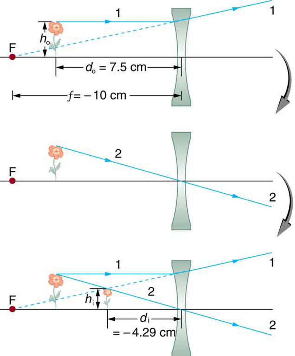
Image Produced by a Concave Lens
Suppose an object such as a book page is held vii.l cm from a concave lens of focal length –x.0 cm. Such a lens could exist used in eyeglasses to correct pronounced nearsightedness. What magnification is produced?
Strategy and Concept
This example is identical to the preceding one, except that the focal length is negative for a concave or diverging lens. The method of solution is thus the same, but the results are different in important means.
Solution
To detect the magnification , we must first find the image altitude using thin lens equation

or its culling rearrangement

We are given that  and . Inbound these yields a value for :

This must be inverted to find :

Or

Now the magnification equation can exist used to observe the magnification , since both and are known. Entering their values gives

Word
A number of results in this instance are true of all case 3 images, equally well as being consistent with (Figure). Magnification is positive (every bit predicted), significant the epitome is upright. The magnification is also less than one, meaning the image is smaller than the object—in this example, a little over half its size. The prototype altitude is negative, significant the epitome is on the aforementioned side of the lens as the object. (The image is virtual.) The image is closer to the lens than the object, since the paradigm distance is smaller in magnitude than the object altitude. The location of the image is non obvious when you look through a concave lens. In fact, since the image is smaller than the object, you may recall it is further abroad. But the image is closer than the object, a fact that is useful in correcting nearsightedness, as we shall encounter in a later department.
(Figure) summarizes the 3 types of images formed by single thin lenses. These are referred to as instance one, 2, and 3 images. Convex (converging) lenses can form either real or virtual images (cases 1 and 2, respectively), whereas concave (diverging) lenses can form merely virtual images (always case iii). Real images are always inverted, merely they can exist either larger or smaller than the object. For example, a slide projector forms an prototype larger than the slide, whereas a camera makes an image smaller than the object beingness photographed. Virtual images are always upright and cannot be projected. Virtual images are larger than the object just in instance two, where a convex lens is used. The virtual image produced by a concave lens is always smaller than the object—a example 3 image. We can see and photograph virtual images only by using an additional lens to grade a real image.
| Type | Formed when | Image type | d i | m |
|---|---|---|---|---|
| Example i | positive, | real | positive | negative |
| Case 2 | positive, | virtual | negative | positive  |
| Case 3 | negative | virtual | negative | positive  |
In Epitome Germination by Mirrors, we shall come across that mirrors tin can form exactly the same types of images as lenses.
Take-Dwelling Experiment: Concentrating Sunlight
Observe several lenses and determine whether they are converging or diverging. In general those that are thicker near the edges are diverging and those that are thicker most the center are converging. On a bright sunny twenty-four hours have the converging lenses outside and try focusing the sunlight onto a slice of paper. Determine the focal lengths of the lenses. Be conscientious because the newspaper may start to burn, depending on the type of lens you accept selected.
Trouble-Solving Strategies for Lenses
Pace 1. Examine the state of affairs to determine that prototype formation by a lens is involved.
Step two. Determine whether ray tracing, the thin lens equations, or both are to be employed. A sketch is very useful fifty-fifty if ray tracing is non specifically required by the trouble. Write symbols and values on the sketch.
Stride three. Identify exactly what needs to be determined in the problem (place the unknowns).
Footstep four. Brand alist of what is given or can be inferred from the problem equally stated (identify the knowns). It is helpful to determine whether the situation involves a case one, two, or 3 image. While these are only names for types of images, they accept certain characteristics (given in (Figure)) that can be of swell use in solving bug.
Step 5. If ray tracing is required, use the ray tracing rules listed well-nigh the kickoff of this section.
Step 6. Most quantitative problems require the use of the thin lens equations. These are solved in the usual manner past substituting knowns and solving for unknowns. Several worked examples serve as guides.
Step seven. Check to see if the answer is reasonable: Does it make sense? If you have identified the type of image (example i, ii, or iii), you should appraise whether your answer is consequent with the type of image, magnification, and so on.
Misconception Alert
We do not realize that light rays are coming from every part of the object, passing through every part of the lens, and all can be used to form the final image.
Nosotros generally feel the entire lens, or mirror, is needed to form an image. Actually, half a lens will grade the aforementioned, though a fainter, image.
Department Summary
Conceptual Questions
It tin exist argued that a flat piece of drinking glass, such every bit in a window, is like a lens with an space focal length. If so, where does it form an image? That is, how are and related?
You can oft meet a reflection when looking at a sheet of glass, particularly if it is darker on the other side. Explain why you can oft come across a double image in such circumstances.
When y'all focus a camera, you adjust the distance of the lens from the film. If the photographic camera lens acts like a thin lens, why can it not be a fixed distance from the picture for both nearly and distant objects?
A sparse lens has two focal points, ane on either side, at equal distances from its center, and should behave the same for light inbound from either side. Look through your eyeglasses (or those of a friend) backward and forrard and comment on whether they are thin lenses.
Volition the focal length of a lens change when information technology is submerged in h2o? Explain.
Problems & Exercises
What is the ability in diopters of a camera lens that has a 50.0 mm focal length?
Your photographic camera's zoom lens has an adjustable focal length ranging from 80.0 to 200 mm. What is its range of powers?

What is the focal length of 1.75 D reading glasses found on the rack in a pharmacy?
You note that your prescription for new eyeglasses is –iv.l D. What will their focal length be?

How far from the lens must the motion picture in a camera be, if the lens has a 35.0 mm focal length and is being used to photograph a flower 75.0 cm away? Explicitly show how you follow the steps in the Problem-Solving Strategy for lenses.
A certain slide projector has a 100 mm focal length lens. (a) How far away is the screen, if a slide is placed 103 mm from the lens and produces a sharp image? (b) If the slide is 24.0 by 36.0 mm, what are the dimensions of the image? Explicitly show how yous follow the steps in the Problem-Solving Strategy for lenses.
(a) iii.43 m
(b) 0.800 past ane.20 chiliad
A doctor examines a mole with a 15.0 cm focal length magnifying glass held 13.five cm from the mole (a) Where is the prototype? (b) What is its magnification? (c) How big is the image of a 5.00 mm diameter mole?
(a)  (on the object side of the lens).
(b) 
(c) 5.00 cm
How far from a piece of paper must you agree your father'southward 2.25 D reading glasses to try to burn down a pigsty in the newspaper with sunlight?
44.4 cm
A camera with a 50.0 mm focal length lens is beingness used to photograph a person continuing 3.00 m abroad. (a) How far from the lens must the film be? (b) If the moving-picture show is 36.0 mm loftier, what fraction of a one.75 m tall person will fit on it? (c) Discuss how reasonable this seems, based on your experience in taking or posing for photographs.
A camera lens used for taking close-upwardly photographs has a focal length of 22.0 mm. The farthest it tin exist placed from the film is 33.0 mm. (a) What is the closest object that can be photographed? (b) What is the magnification of this closest object?
Suppose your 50.0 mm focal length camera lens is 51.0 mm away from the film in the camera. (a) How far away is an object that is in focus? (b) What is the height of the object if its image is 2.00 cm loftier?
(a) What is the focal length of a magnifying glass that produces a magnification of 3.00 when held 5.00 cm from an object, such equally a rare coin? (b) Calculate the power of the magnifier in diopters. (c) Discuss how this power compares to those for store-bought reading glasses (typically ane.0 to 4.0 D). Is the magnifier'southward power greater, and should information technology be?
(a) 
(b) 
(c) Much greater
What magnification will be produced by a lens of power –iv.00 D (such every bit might be used to right myopia) if an object is held 25.0 cm abroad?
In (Figure), the magnification of a book held seven.fifty cm from a ten.0 cm focal length lens was found to be 3.00. (a) Find the magnification for the volume when it is held viii.fifty cm from the magnifier. (b) Practice the same for when information technology is held 9.l cm from the magnifier. (c) Comment on the tendency in m as the object altitude increases as in these two calculations.
(a) +6.67
(b) +20.0
(c) The magnification increases without limit (to infinity) as the object distance increases to the limit of the focal distance.
Suppose a 200 mm focal length telephoto lens is being used to photograph mountains 10.0 km abroad. (a) Where is the epitome? (b) What is the elevation of the epitome of a thousand thousand loftier cliff on one of the mountains?
A photographic camera with a 100 mm focal length lens is used to photograph the sun and moon. What is the top of the image of the sunday on the pic, given the sun is  in diameter and is
  abroad?

Combine thin lens equations to bear witness that the magnification for a thin lens is determined past its focal length and the object distance and is given past  .
.
Glossary
- converging lens
- a convex lens in which light rays that enter it parallel to its centrality converge at a single point on the opposite side
- diverging lens
- a concave lens in which light rays that enter it parallel to its axis bend abroad (diverge) from its axis
- focal point
- for a converging lens or mirror, the point at which converging lite rays cantankerous; for a diverging lens or mirror, the bespeak from which diverging calorie-free rays announced to originate
- focal length
- distance from the middle of a lens or curved mirror to its focal point
- magnification
- ratio of epitome elevation to object superlative
- ability
- changed of focal length
- real paradigm
- image that can be projected
- virtual paradigm
- epitome that cannot be projected

Source: https://opentextbc.ca/openstaxcollegephysics/chapter/image-formation-by-lenses/
Posted by: gallawaysagell.blogspot.com
0 Response to "What Is The Power In Diopters Of A Camera Lens That Has A 50.0 Mm Focal Length?"
Post a Comment